This is the story of how I built my Android/IOIO/OpenCV-based interactive plotter, as well as the soon-to-be-released motor control library for the IOIO. I'll tell the story of the plotter from the bottom up, which is the order in which I've designed and built it. But before diving into the geeky technical details, a few words about the final product.
It started with me looking for a cool example application for the motor control library I was about to develop for the IOIO, and have this application something I can present in Maker Faire. I wanted it to demonstrate the ability to control some multi-axis machine in a simple, reliable and precise way using high-level Java code running on an Android or a PC. I finally decided on the plotter, as it seemed like a fun thing to make as well as an interesting piece to exhibit. The plotter is based on a very elegant design, which unfortunately isn't my idea (just Google for "whiteboard plotter"). Since building yet-another-one is boring, I wanted to make this one with a twist, taking advantage of the fact that I can easily put an Android device in the system. So my plotter is interactive in that you take a picture with it and it would immediately convert it to paths (via edge detection) and plot them.Now we're ready for the geeky stuff :)
Ultra-Productive Development Environment
My friend and colleague Anton Staaf, has introduced me to a really cool development strategy he's been using on his projects. He developed this nice little "shell" library, which is essentially a simplified, very portable command shell, to which it is very easy to add new commands. I borrowed his code, and ported it to the PIC24, using the USB CDC as the underlying serial link. Shortly after, I had a IOIO board which I could plug into the USB port of my PC, open a "screen" session to and run commands to exercise whichever new features I'm working on. Combined with the device-mode bootloader of the IOIO-OTG, I was able to have super fast cycles of code-compile-flash-test. It was really fun to work like that. I'm hoping to eventually release this shell-app for the IOIO for others to hack with - it's totally awesome!Another tool which served me really well here is the XProtoLab from Gabotronics. Since this library is all about generating perfectly synchronized, precisely-timed signals, I needed a way to validate the output signals. I don't have a scope or a digital analyzer, but the XProtoLab is a tiny, beautifully designed, tiny oscilloscope, logic analyzer and signal generator. I bought this one second hand for $30 a while back and it is worth its weight in gold. Highly recommended!
Now I was in good position to start playing around with some ideas for how my library will work, which I eventually ported into the proper IOIO app firmware.
H-A-R-D-R-E-A-L-T-I-M-E
OK, so I develop realtime software for a living, but I never before got to this level of realtime...I initially drafted the following design principles:
- The IOIO will play the role of a sequencer. It will have a buffer of "cues", which keeps getting filled by the client (Android or PC). Those cues are essentially "over this period of time, I want this channel to do this and that channel to do that". A channel can be for example a stepper motor pulse train, a PWM signal for a DC motor or a servo or a digital output pin.
- As usual with the IOIO library, I want this to happen with as little as possible CPU intervention, so that it can run in parallel with all the other IOIO functions. So I decided I'll use the output compare modules for generating all the pulse signals and a timer for timing the cues.
- But stepper signals are slightly tricky, as you want a precise number of steps over the period of the cue. Not one too many, not one too little. Ever. So one might generate those pulses one-by-one, but that would place a lot of burden on the CPU and would be very difficult to time correctly when multiple channels are involved. So I decided I'll just let the pulse trains run freely during a cue, and just be really really precise about stopping them at the right time, before they generate an extra pulse.
So, OK, one might think that setting a timer to interrupt at the highest possible priority should suffice, but it really doesn't, unless you want to be really way too conservative with how close you allow your last step in every cue to get to the cue point. But that would put a very serious limitation on the maximum pulse rate, which I didn't want to do.
It took my some time to convince myself that C can't cut it. You just can't really know how many cycles your code is going to take. And even if you could, this could change the next time you upgrade your compiler. So I reverted to assembly. It was actually a lot more fun than I expected, after not having done this for years. And the end-result is something I'm really really happy with! Cycle-accurate timings for everything. I know exactly when each instruction runs with respect to the output waveforms and everything is super-fast, so it doesn't place any significant overhead on the CPU. You can do up to about 30KHz signals, up to 9 such in parallel, in addition to twenty-something binary outputs (e.g. for controlling the stepper direction, solenoids, or LEDs), without ever missing a step jittering on the timing by as little as one CPU cycle.
Of course, it took me about 10 times to complete than it would have in C...
Here's a little (underground) video I shared a while ago, demonstrating some early stages of the motor control library:
Protocol Glue
From this point, bootstrapping this library to the IOIO protocol was pretty straightforward, and shortly after I had a semi-baked Java API for feeding the sequencer. The current API is pretty bare-metal, and I'm thinking about providing it with some higher level abstraction layer when I release it, or at least a decent set of handy utilities. For the time being, I developed some utilities that are specific to stepper motors, which is what I needed for the plotter.
Plotter Design
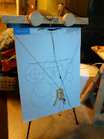
Finally came the time to make the plotter. The design is pretty simple: two pulleys driven by stepper motors controlling the length of two strings. The two strings are joined in one point attached to the carriage. A rather simple geometric transformation can tell you how long you want each of the strings to be in order to get the carriage to a given point on the sheet in XY coordinates.
On the carriage is a sharpie. In order to minimize the effect of the carriage swinging on the position of the tip of the sharpie, the hanging point, where the strings connect needs to be as close as possible to the tip. This way, even if the carriage tilts a little, the tip won't deviate by a whole lot.

I found a neat little trick for the carriage design: when drawing, the carriage is supported by two ball casters and the tip of the sharpie. This way the sharpie stays perpendicular to the sheet. In order to raise the sharpie (for moving the carriage without plotting), a third ball caster is mounted on an actuated linear bearing, driven by a small hobby servo. The servo can push this third caster into the sheet, so that it is "deeper" than the tip of the sharpie, thus causing the carriage to be supported on the three casters and the sharpie tip to float.

 Oh, and remember that I just used the fancy term "linear bearing", causing you to imagine some precision machined awesomeness? Think more like a piece of a shampoo bottle pump in this case :) What can I say, I just hate waiting for parts to arrive or worry about how to fabricate the perfect bearing, when all I really care about is getting this app up and running...
Another little trick I found is for mounting the main assembly (with the motors and pulleys) on the easel: I used some square pieces of plastic, originally intended for hot cups, and bent them with the hot air gun I used for soldering. It ended up pretty cool, and I can easily unmount the thing for transportation.
And of course, the IOIO is mounted on the front, and a pair of DRV8825 stepper drivers behind it to help with the heavy-lifting. I dialed them to about 1A per motor, which seems to work well.
Now, Plot!

There's this part in a project when the hardware is pretty much done and now it's all "just a simple matter of software", as my friend Ed likes to joke. But at this point, having all these million layers of infrastructure at my disposal, I just couldn't wait to draw something with it and see if it's any good. For all I know, I might have a million problems hidden. I coded like crazy for a couple of days, until finally plotting a first circle! Well, let's call it circle-ish, since it did uncover some small mechanical issues that needed addressing. But pretty much, the entire stack of electronics and software worked flawlessly! I wrote some basic utilities to do the coordinate transformations and to expose a high-level Plotter API, which gets an arbitrary list of paths, each represented by x(t), y(t) and plots them.
Pimp Your Plotter

Since this piece is to be presented, some aesthetics can't hurt. I coincidentally noticed that the pulleys look a lot like yo-yo's and decided to have fun with this concept. My friend Ali took me for an awesome tour in his workshop and let me cut some pieces of MDF on his laser cutter. It's funny that the only precision part in this entire system is the decoration :D
Finally: The App Layer
So many layers on layers on layers, I finally had a working plotter and it was time for the application. It's been a long time since I wanted to get my hands dirty with OpenCV for Android. It is 100% pure awesome! Makes image manipulation and standard computer vision algorithms really simple to implement. I developed a simple GUI that allows you to pick a picture from your Android gallery (local storage, Web albums or capture an image from the camera), and then interactively tweak the parameters of a Canny edge detector. The detected edges are displayed in red against a grayscale image, so you can easily see what result you are going to get and keep moving the sliders until you're happy.thinning the resulting edges, or otherwise a single edge may actually be two-pixel thick at times, which makes it really annoying to convert into paths. I used the algorithm proposed here (thanks, guys!) and implemented it pretty easily with OpenCV. Last, I needed to trace the edges into paths. I did this step pretty dumbly, because I started to run out of time and juice. In the future, it could be pretty nice to: Then, I found that an essential step I needed to take is
 - Smooth the edges rather than just connect pixels coordinates with straight lines. A nice algorithm to borrow ideas from is here.
- Be clever about the ordering of paths within an image, so that to attempt minimize the total length of travel of the carriage. In the current implementation, the ordering is pretty stupid, causing the carriage to move from side to side way more than is necessary, significantly slowing down the process.
Aftermath
This weekend I'm going to present this project, along with some other IOIO projects in the Maker Faire Bay Area 2013. If you happen to be around, drop by to say hi. Special thanks to my good friend Al Linke, who made the video shown at the top. Al has made some awesome IOIO-based projects himself, and is going to share the booth with me in Maker Faire.
I intend to release the motor control library within a few weeks for everybody to enjoy. I hope it will pave the way for driving 3D printers and other CNC machines with a IOIO/Android combo, which seems to me like an elegant way for giving these machines a great user interface, standalone computing and connectivity on the cheap.
Some more fun pictures for those who persisted this far.


This is awesome stuff! I'm really looking forward to getting my hands on the motor control functionality in the IOIO board. Some years ago I built a home made CNC machine from old printer stepper motors and 2 cross vices all controlled via a parallel port to an old lappy. Now I can easily upgrade to USB and make it more accurate too :)
ReplyDeletePlease come out with this I wanna use it!!
ReplyDeleteGorgeous!
ReplyDeleteincredible work !
ReplyDeletevery interested by the motor library .. especially for working on a new lib for reprap . Controlling with ioio and any android mobile. Please email me if you're in a sharing mood :)
thx
I'm actively working on releasing this code officially, as well as some other long outstanding changes and bug-fixes. Unless something surprising happens, this should be out in a few weeks.
Deletesounds very good. thank you. I'm developer and working on a reprap small printer design project . I "really" dream to make a ioio ramps :) ( maybe a simple ramps adaption ? needs only 4 step drivers and some power lines) and then a lib to control those steppers and parse gcode.
Deletethen a nice android app to play with all that .
Not for next week but definitely in the list . thx to you !
Update:
ReplyDeleteIOIO library and firmware v5.00 with the motor control API mentioned here, as well as the Android app for this specific plotter have been released on my github account.
Ytai, it's brilliant, plotter with graceful motion!
ReplyDeleteDear Ytai
ReplyDeleteI am trying to use your plotter Software and would need a little help (Explanation) from your side.
Can you help me to give me a hint about the steptime you are using in
public Plotter(float stepTime)
private Plotter plotter_ = new Plotter(1e-3f);
how can i calculate it for my Setup ?
Hello Ytai, I´m happy and surprised for your work, I want make sommething big and stupid hehehehe (it´s my project), sorry for my English it's not my language, I want control to steep motor with "driver steep motor", only have pin steep and pin direction, but I´m trying with DigitalOutPut or pwm but I can´t, I have ioio-otg, How can I make to send cue to Driver Steep and move my Steep motor?
ReplyDeleteThis should help:
Deletehttps://github.com/ytai/ioio/wiki/Motor-control
hello man, Thank for to replies, You realy helpme, I make upgrade the new firmware to my IOIO-OTG for use the new library (504), it was to easy write the new firmware, I can controller "driver steep motor" it to easy Thank, but In the last library (330), I made a class to create a object IOIO whitout IOIOActivity since of class IOIOService and put in the object singelton this allowed pass Activity to Activity and keep one connection, it was working, I need make this with the new librery (504), I don't kwon need create thread of some class, create a new instance of a class special or create new Object? sorry for my english, In finding I need create a IOIO instance in the firt Activity and pass between Activitys and never lost the connection.
DeleteThank you
how long does it takes for 1 picture?
ReplyDeleteCould be anywhere between 10-30 minutes, depending on how dark the image is. It could be sped up to some extent, but I didn't want to do that because watching it go is part of the fun :)
DeleteThank you for sharing, it's really helped me...
ReplyDeleteVery nice article...
Great idea! Congrats! :)
ReplyDeleteHey Ytai, I became a fan of you after watching the videos...!!!. I also want to make one like this. Will you please help me...
ReplyDeleteThanks! I can try to help, but be prepared to have to dive deep and do some of the work yourself. I don't have any actual plans for the build, it is mostly parts I pulled together from stuff I had lying around the house. The software is all available in my GitHub account. I will be happy to answer specific questions on email (ytaibt on the Google mail service).
ReplyDeleteThanks! I can try to help, but be prepared to have to dive deep and do some of the work yourself. I don't have any actual plans for the build, it is mostly parts I pulled together from stuff I had lying around the house. The software is all available in my GitHub account. I will be happy to answer specific questions on email (ytaibt on the Google mail service).
ReplyDeleteHi. The project is great. I would like to try to do the same. But before buying the components (IOIO board and mototres I like) I would like to know if you can check the connection scheme of the board. That is to say to the pins that are connected the motors. I imagine it will look like arduino. I would also like to know if there is any plane with the dimension of the strings and the distances to which they should be put on the Easel. I imagine that for the drawing to be the expected one will have to put the cords of a concrete size and so that the motors know how many turns they have to give to have the same paths.
ReplyDeleteThank you very much.
a greeting.
Thanks!
DeleteI don't have any build plans for this project. The hardware setup is fairly straightforward and adapting the code to match the physical dimensions of the plotter or the parameters of the steppers etc. is a matter of changing a few constants.
You can study the code to understand how things should be connected. If you understand how to connect a stepper driver to a microcontroller you should be fine.
Sorry, English is not my mother tongue. I want to know the model of the motor driver to copy this experiment
ReplyDeleteSee these:
ReplyDeletehttps://www.pololu.com/category/120/stepper-motor-drivers
I believe I used the A498 one, but they're all very similar as far as their digital interface.
Hi, I really like this project and it is inspiration for one of my own. I am trying to use stepper motors with my own ioio otg board. However when i try to set a pin in open drain mode using the following line:
ReplyDeletepwmO_ = ioio_.openPwmOutput(new DigitalOutput.Spec(11, Mode.OPEN_DRAIN), 1000);
It will not compile because of the "Mode". I get the following error "error: cannot find symbol variable Mode"
Do you know what the problem may be here and how to fix it?
You need to write DigitalOutput.Spec.Mode.OPEN_DRAIN.
DeleteWhat are you hoping to achieve with controlling stepper motors with a PWM output? You won't be able to actually control the number of steps precisely this way.